国产精品日日做人人爱,国产男女无遮挡猛进猛出,1000部精品久久久久久久久,大陆熟妇丰满多毛XXXX
<label id="o8frx"><strong id="o8frx"></strong></label>
<tt id="o8frx"></tt>
<abbr id="o8frx"><strong id="o8frx"></strong></abbr>
tcm:115-2219208-64
要使用網站的所有可用功能,必須在瀏覽器中啟用 JavaScript。
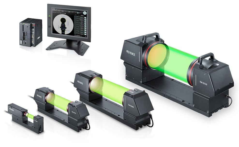
Telecentric Measurement System TM-X5000 Series
搜索
Manual Top
Read me
Introduction
Symbols
Precautions
Trademarks
Software information
Safety Information for TM-X5000 Series
General Cautions
Precautions for use
Measures to be taken when an abnormality occurs
Operating environment and conditions (precautions on installation/transportation)
Maintenance
Caution on wiring
For Optimal Performance of the TM-X5000 Series
Precautions on Regulations and Standards
CE and UKCA Marking (Controller/Head)
CE and UKCA Marking (Hardware Key)
CSA Certificate
North American Regulations
Best Management Practice for Perchlorate Materials - California only
KC mark (Republic of Korea) (for Dedicated monitor for TM-X only)
Safety Precautions on LED product
Software License Agreement
Changes to each version of the TM-X5000 Series
Major Changes to Ver. 1.1
Main Changes to Ver. 1.2
Main Changes to Ver. 1.3
Main Changes to Ver. 1.4
Main Changes to Ver. 1.5
Compatibility
Chapter 1 Preparation for Use
System Configuration
Part Names and Functions
Controller (TM-X5000)
Head (TM-X5006 / TM-X5040 / TM-X5065/ TM-X5120)
Dedicated monitor for TM-X (TM-MP120)
Communication Expansion Unit (CB-NEC20E/CB-NEP20E/CB-NPN20E)
List of Optional Products
Chapter 2 Installing the TM-X5000 Series
Installation and Wiring
Installing the Head
Attaching the Protective Cover
Installing the Controller
Installing the Communication expansion unit
Installing the Dedicated Monitor for TM-X
Wiring
Connecting the Power to the Controller
Connecting the Power to the Dedicated monitor for TM-X
How to use the terminal block
Chapter 3 Setup/Run
Basic Operation
Workflow from Connection to Running
Basic Operation of the Tool Settings
Convenient Operation of the Tool Settings
Layout of the Screen
[Setup] Mode
[Run] Mode
Program Settings Menu
Head Settings
Selecting a Recipe
Register Reference Image
Position Correction
Measurement Settings
Output Settings
Edit Menu
Program Operation
Archived Image
Operation Menu for Archived Image
Batch Test
Statistics
Trend graph
Histogram
Chapter 4 Global Settings/Utility
Global Settings
Communications & I/O
System
Date/Time
Language
Reboot
Security
System Information
Utility
I/O Monitor
RS-232C Monitor/Ethernet Monitor
EtherNet/IP Memory Monitor
PROFINET Memory Monitor
PLC-Link Memory Monitor
EtherCAT Memory Monitor
Statistics
Memory Setting
Archived Image Settings
Remove External Media
Head-to-head Adjustment Setting
Head-to-head Adjustment Execution
Chapter 5 I/O Control and Timing Charts
List of Communication Commands for Control
Notes on Command Input/Output
List of Operation Modes and Available Input Commands
Trigger
System control
Change inspection program
Measurement control
I/O control
Utility
System
Fetching Measurement Results
Head-to-head Adjustment Execution
Image Composition
Simple Monitor View
Setting change
Head Adjustment
Input/Output and Control Using EtherNet/IP
Controller EtherNet/IP Communication Specifications
Allocation Conditions of Cyclic Communication Data
Changing the EtherNet/IP Settings
Outputting Measurement Data Using EtherNet/IP Cyclic Communications (Data Output)
Controlling the Controller with EtherNet/IP Cyclic Communication (Command Control)
Controlling the Controller with EtherNet/IP Cyclic Communication (Change Recipe Number)
Troubleshooting
Communicating with the Controller Using EtherNet/IP Message Communications
Overview of Control/Data Output Using PROFINET
Controller PROFINET Communication Specifications
Allocation Conditions of Periodic Communication Data
Changing PROFINET Settings
Outputting Measurement Data Using PROFINET Periodic Communications (Data Output)
Controlling the Controller with PROFINET Periodic Communication (Command Control)
Controlling the Controller with PROFINET Cyclic Communication (Change Recipe Number)
Troubleshooting
Overview of Control/Data Output Using EtherCAT
Standard Specifications for the EtherCAT Unit (CB-NEC20E: Optional)
Models that Support EtherCAT Connection
Allocation Conditions of Cyclic Communication Data
Changing EtherCAT Settings
Outputting Measurement Data Using EtherCAT Cyclic Communications (Data Output)
Controlling the Controller with EtherCAT Cyclic Communication (Command Control)
Controlling the Controller with EtherCAT Cyclic Communication (Change Recipe Number)
Troubleshooting
Control/Data Output via the PLC-Link
Models that Support the PLC Link Connection
Preparing the PLC
Changing the PLC-Link Settings
Outputting the Measurement Data with PLC-Link
Controlling the Controller via PLC-Link
Troubleshooting
Input/Output and Control Using the I/O Terminal
Functions available with the I/O terminal on the controller
Terminal Block Interface (OUT)
Terminal Block Interface (IN)
Parallel I/O Interface
Using command inputs via I/O terminals
I/O command inputs available on the controller
I/O command control procedures
Outputting judgment values via I/O terminals
Timing chart
Chapter 6 Specifications
Specifications
Controller
Head
Dedicated monitor for TM-X
Cable
Extension cable repeater
Communication expansion unit
Characteristics
Measurement area
Temperature Characteristics (examples)
Reference Surface of Head
Dimensions
Controller (TM-X5000)
Head (TM-X5006 / TM-X5040 / TM-X5065 / TM-X5120)
Transmitter-to-receiver cable (OP-87033/OP-87034)
Head connection cable (CB-C3R / CB-C5R / CB-C10R)
Repeater for head connection extension (TM-CX10U) / Head connection extension cable (CB-C10RX)
Protective cover (OP-88575/OP-88576/OP-88775)
Dedicated monitor for TM-X (TM-MP120)
Dedicated monitor mount (OP-87262)
Mouse (OP-87506)
Chapter 7 TM-X Navigator
TM-X Navigator
Operating Environment
Installation method
Activation
Simulator
Start the Simulator
Differences Between the Controller and Simulator
Folder configuration on the PC
CAD Import
Appendix
Error Messages
System error messages
Normal errors
Telecentric Measurement System
TM-X5000 Series
User’s Manual
關閉